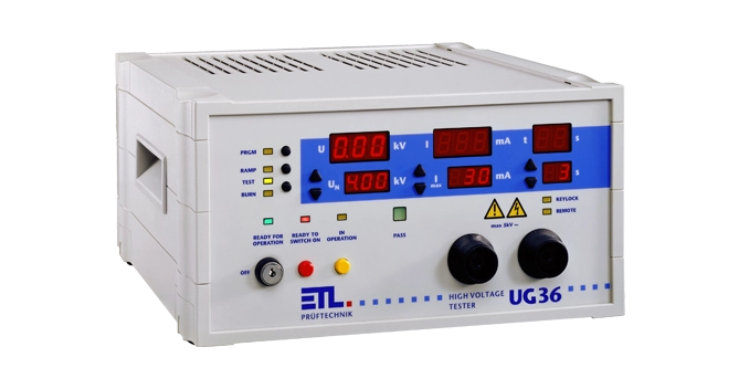
Specifications, device characteristics
Test Voltage:
Range:
100 - 6 000 V AC
Resolution, digit:
10 V
Measurement uncertainty, accuracy:
1 % of measured value +/- 2 digits
Output frequency:
50 Hz / 60 Hz, depending on mains
Wave form:
sinusoidal according to EN 61180, depending on mains
Voltage stability:
regulated output voltage, PI-regulated
Zero-voltage switching:
The test voltage is switched on and off at zero crossing
Ramp function:
freely programmable
Display for actual value:
LED-Display 13 mm, red
Display for desired value:
LED-Display 10 mm, red
Test Current:
Maximum trip current:
0.1 - 10 mA
Resolution, digit:
0.1 mA
Measurement uncertainty:
1 % of measured value +/- 3 digits
Safety current limited:
< 12 mA, gemäß EN 50191
Display for actual value:
LED-Display 13 mm, red
Display for desired value:
LED-Display 10 mm, red
Test Time:
Range:
1 s - 99 min, continous
Ramptime range:
0.5 s - 99 s
Resolution up to 10 s:
0.1 s (digit)
Resolution > 10 s:
1 s
Measurement uncertainty:
+/- 1 digit
Start of test time:
The test time will only be started if the set test voltage is reached.
Minimum test time
1 s
Display for actual value:
LED-Display 13 mm, red
Display for desired value:
LED-Display 10 mm, red
General data:
Mains supply:
230 V, 50 Hz / 60 Hz
Mains connection:
Schuko-plug
Tolerance mains voltage:
+/- 10 %
Current consumption:
max. 2 A
Fuse:
8 A, T, 5 x 20 mm, 250 V
Displays:
LED, permanent display of actual and desired values
Setting of test parameters:
manually or fully automatic via interface (Windows DLL, ASCII, .net framework assembly, DataView)
Programming:
15 sets of parameters, freely programmable
Error signaling:
acoustic, optical and via interface
Outputs from panel:
2 x high voltage outputs (2-poled socket)
Dimensions (B x H x T):
308 x 168 x 273 mm
Weight:
approx. 13.9 kg
Casing:
synthetic material, RAL 7035
Basic equipment:
manual, mains cable, safety circuit plug
Calibration:
Factory-calibration, traceable to national standards, incl. calibration certificate
DAkkS-calibration according to DIN EN ISO / IEC 17025 optional available
Environmental Conditions:
Casing:
IP20
Humidity:
max. 80 %, non condensing
Allowed range of temperature:
+ 5 up to + 40 °C
Max. height above sea level
2 000 m
Cooling:
passive, active cooling optional available
Interfaces:
Control- / Digital-IO:
start, stop, result GOOD, result ERROR and test running
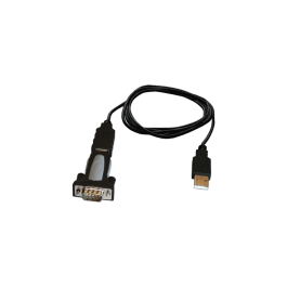
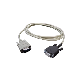
RS232 for remote control:
Computer connection both for terminal programme and software control, as well as optionally for operating a log printer.
CAN interface:
for expanding the test system with additional features and further external expansions stages
Additional Functions:
Ramp function:
The voltage ramp is freely programmable. The voltage is ramped to the desired test voltage, only then the test time starts.
Error detection:
switch off on threshold value and by peak detection
Contact monitoring:
monitoring of contact to the test object with suitable contacting device (4-pole)
German patents: 100 11 466.0 und 100 11 345.1
European patents: 01 105 568.8 und 01 105 567.0
Cable break monitoring:
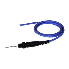
monitoring the test leads for open circuit
German patents: 100 11 466.0 und 100 11 345.1
European patents: 01 105 568.8 und 01 105 567.0
Minimum current monitoring:
monitoring of preset minimum current during the test
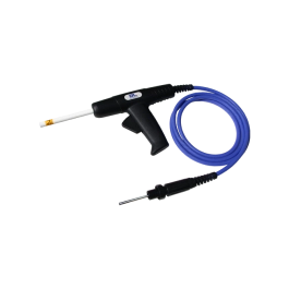
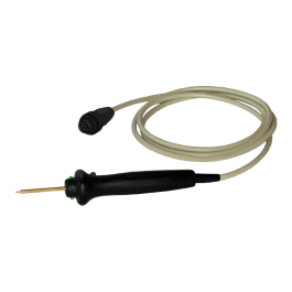
Automated test start:
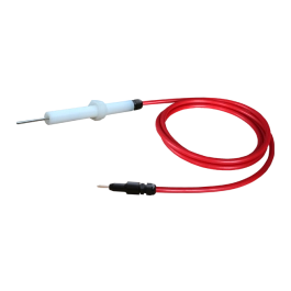
The ETL test pistol HTP06C monitors the contact to the test object via a special HW structure.
German patents: 100 11 466.0 und 100 11 345.1
European patents: 01 105 568.8 und 01 105 567.0
Expanded Device-Setup:
Ramp function:
individual setup
Ramp options:
individual setup for amp-up time and ramp-down options
Key lock:
individual setup
Signal configurator:
individual setup for digital result outputs
Buzzer options:
individual setup of acoustic signals
LED-Display:
individual LED brightness
Start options:
individual setup of start modes
Language and mode selection for external printer:
printout at pass, fail, continous or switch off
formats: list or CSV
Start Options for Testing:
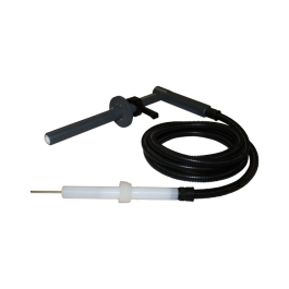
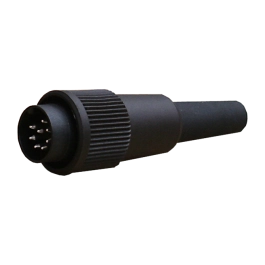
Start and stop signal via test pistol:
Special 4-wire-technology for automated test start and connection monitoring. The test will only be started if both test pistols are connected to the test object.
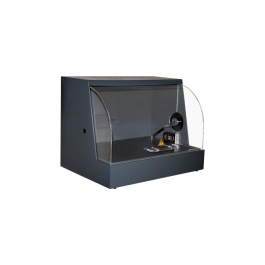
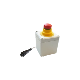
Start via safety circuit:
The test will only be started if the testing cage is closed.
Start button on device:
The test is started by pressing the button on the front of the device.
Start via serial interface:
Start via higher-level control system (SPS oder PC)
Start via digital inteface:
Start via digital IO such as PLC, foot switch, pushbutton, etc. ...
Start options:
individual setup of start modes
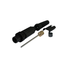
Outputs - Test Object, Security Components:
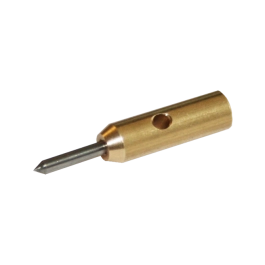
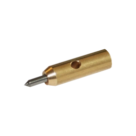
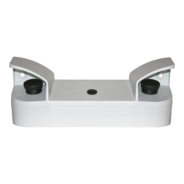
High-Voltage outputs:
Contact is made via 2 potential-free high-voltage outputs (HV installation sockets HVS06C). The outputs are each 2-pole (A Ø 6 mm, I Ø 2 mm). Contact monitoring can thus be achieved in an automated environment.
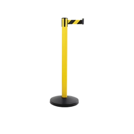
Safety circuit:
to implement the appropriate safety circuit in accordance with EN 50191
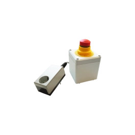
Signal light connector:
for connecting a signal light combination in accordance with EN 50191
Electrical safety and norms:
EN 61010-1:
Safety requirements for electrical equipment for measurement, control, and laboratoy use
EN 61326-1:
Electrical equipment for measurement, control and laboratory use - EMC requirements
EN 61000-3-3 / EN 61000-3-2:
Electromagnetic campatibility (EMC)
EN 50191:
Erection and operation of electrical test equipment
Contamination level:
2
Protection class:
1
Interfaces
Control-Interface/ Digital IO:
Digital interface for connecting a PLC, a foot switch or a result or operating panel with signals such as start, stop, result good / error and test running.
RS232 / PC-Interface:
For connection to the PC. All test parameters can be set by the higher-level control system - the desired test setpoints are set automatically by the device. The interface also allows permanent data acquisition and monitoring of status information. On the PC side, the DataView data management package or drivers (Windows DLL, ASCII, .net framework assembly) are available for your own PC application.
RS232 / ASCII printout:
For direct connection to a terminal programme or a report printer. As an alternative to PC remote control, the tester permanently transmits the results in ASCII format. The language of the printout can be set.
CAN-Interface:
For expanding the test system for additional features and further expansion stages. Any number of ETL devices and CAN components can be linked and remotely controlled via this interface.
Safety circuit:
For implementing the appropriate safety circuit in accordance with EN 50191. 3 different wiring options are available for standard-compliant testing with test pistols, test cages or within a transfer line.
Signal light connector:
For connecting a signal light combination with one red and one green rotating beacon in accordance with EN 50191.