Specifications, Device Characteristics
Test Current
Range:
> 10 A AC
Resolution, digit:
0.1 A
Measurement uncertainty, accuracy:
1 % of measured value +/- 2 digits
Wave form:
sinusoidal, depending on mains
Display for actual value:
LED-Display 13 mm, red
Display for desired value:
LED-Display 10 mm, red
Resistance
Range:
1 - 500 mΩ
Resolution, digit:
1 mΩ
Measurement uncertainty:
1 % of measured value +/- 2 digits
Display for actual value:
LED-Display 13 mm, red
Display for desired value:
LED-Display 10 mm, red
Test Time
Range:
1 s - 99 min, continuous
Ramptime range:
0.5 s - 99 s
Resolution up to 10 s:
0.1 s (Digit)
Resolution display > 10 s:
1 s
Measurement uncertainty:
+/- 1 digit
Start of test time:
The test time will only be started if the set test voltage is reached.
Minimum test time:
1 s
Display for actual value:
LED-Display 13 mm, red
Display for desired value:
LED-Display 10 mm, red
General Data
Mains supply:
230 V, 50 Hz / 60 Hz
Mains connection:
Schuko-plug
Tolerance mains voltage:
+/- 10 %
Current consumption:
max. 8 A
Fuse:
8 A, T, 5 x 20 mm, 250 V
Displays:
LED, permanent display of actual and desired values
Setting of test parameters:
manually or fully automatic via interface (Windows DLL, ASCII, .net framework assembly, DataView)
Programming:
15 sets of parameters, freely programmable
Error signalling:
acoustic, optical and via interface
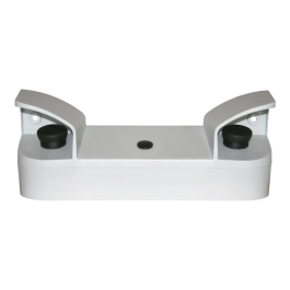
Outputs from panel:
2 x sockets for DUT contacting, optional on back side
Dimensions (W x H x D):
308 x 168 x 273 mm
Weight:
approx. 15.8 kg
Gehäuse:
synthetic material, RAL 7035
Basic equipment:
manual, mains cable, safety circuit plug
Calibration:
factory calibration, traceable to national standards, incl. certificate
DAkkS-calibration according to DIN EN ISO / IEC optional available
Environmental Conditions
Casing:
IP20
Humidity:
max. 80 %, non condensating
Allowed range of temperature:
+ 5 up to + 40 °C
Max. height above sea level:
2 000 m
Cooling:
passive, active cooling optional available
Interfaces
Control- /Digital-IO:
start, stop, result GOOD, result BAD and test running
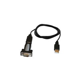
RS232 for remote control:
computer connection for terminal programming and controlling by customer specific software applications, optional usage of a protocol printer
CAN interface:
for expanding the test system by additional devices
Expanded Device-Setup
Key lock:
individual setup
Signal configurator:
individual setup for digital result outputs
Buzzer options:
individual setup of acoustic signals
LED-Display:
individual LED brightness
Start options:
individual setup of start modes
Language and mode selection for external printer:
printout at pass, fail, continuous or switch off
Formats: List or CSV
Options for Test Start
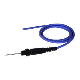
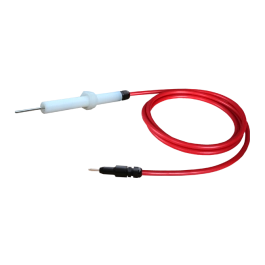
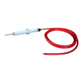
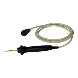
Start via test probe signal:
The test starts by pressing the start button included in the test probe.
Automatic start via safety circuit:
The test can be started by closing the test cage.
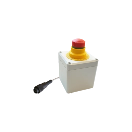
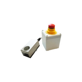
Start button on the device:
The test is started by pressing the button on the front of the device.
Start via serial interface:
Start via higher-level control system (PLC or PC)
Start via digital interface:
Start via digital IO such as PLC, footswitch, pushbutton, etc. ...
Start options:
individual setup of start modes
Outputs - DUT, Safety Components
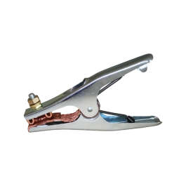
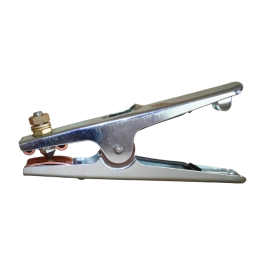
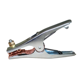
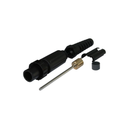
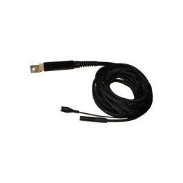
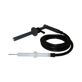
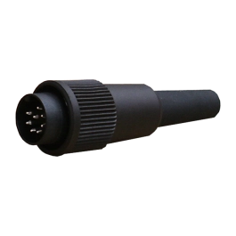
Socket for DUT housing contact:
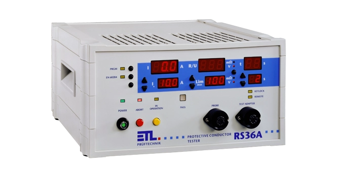
7-pole socket on the front:
Connection for contacting the test object via a test probe with start button and result LEDs. Optionally, a clamp can also be plugged in for permanent connection.
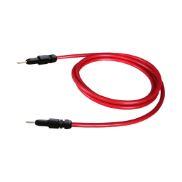
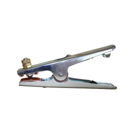
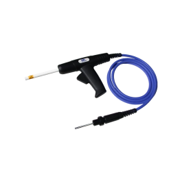
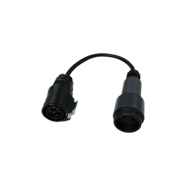
Socket for DUT mains:
4-pole socket on the front:
Connection for contacting the test object via a suitable cable adapter with e.g. Schuko plug or clamps for test objects with open cable ends. Optionally, a second test probe or a tap-off terminal can be plugged in for a permanent connection.
Electrical Safety and Norms
EN61010-1:
Safety requirements for electrical equipment for measurement, control, and laboratory use
EN61326-1:
Electrical equipment for measurement, control and laboratory use - EMC requirements
EN 61000-3-3 / EN 61000-3-2:
Electromagnetic compatibility EMC)
EN 50191:
Errection and operation of electrical test eqipment
Contamination level:
2
Protection class:
1
Interfaces
Control interface / Digital-IO:
Digital interface for connection to a PLC, footswitch or a remote panel including signalling of start, stop, good result, bad result, faulty test object and in operation.
RS232 / PC-interface:
For connection to the PC. All test parameters can be set by the higher-level control system - the desired test values are automatically set by the device. The interface also allows permanent data logging and monitoring of status information. On the PC side, the DataView data management package or drivers (Windows DLL, ASCII, .net framework assembly) are available for your own PC application.
RS232 / ASCII printout:
For direct connection to a terminal programme or a protocol printer. As an alternative to PC remote control, the tester permanently transmits the results in ASCII format. The language of the printout can be set.
CAN-Interface:
For expanding the test system for additional features and further expansion stages. Any number of ETL devices and CAN components can be linked and remotely controlled via this interface.