High Voltage Testing HV-AC 5 000 V AC - 100 mA:
Test Voltage:
Range:
100 - 5 000 V AC
Resolution, digit:
10 V
Measurement uncertainty:
1 % of measured value +/- 2 digits
Output frequency:
45.0 – 65.0 Hz, resolution 0.1 Hz
Waveform:
Sinusodial according to EN 61180, electronically generated
Voltage stability:
Output electronically regulated (PI-controller)
Maximum output power:
> 500 VA, including active DUT discharge
Test voltage switching:
Test voltage is switched at zero voltage crossing
Ramp function:
Freely programmable from 0.2 s up to 6 000 s, including start voltage
Test Current:
Maximum trip current:
0.1 – 100.0 mA
Minimal trip current:
0.0 – 100.0 mA
Resolution:
0.1 mA
Measurement uncertainty:
1 % of measured value +/- 3 digits
Short circuit current:
> 200 mA
Test Time:
Range:
0.5 s – 6 000 s, longer test time optional available
Ramptime range
0.2 s – 6 000 s
Resolution:
0.1 s
Measurement uncertainty:
+/-10 ms
Start of test time:
The test time will only be started if the set test voltage is reached
Other:
Error detection:
Limit Detection, Peak Detection and Arc Detection
Current and voltage measurement:
Directly at high voltage potential
Contact monitoring *:
The contact to the DUT is monitored when using a suitable contacting unit (4-pole)
Test lead break monitoring *:
Monitoring of the test lead if there is a cable break
Test pistol start automatic *:
The test can be started by contacting the DUT with the test pistols
Earthing:
Potential free and suitable for test pistol operation according to EN 50191
* Patents: DE: 100 11 466.0 und 100 11 345.1, EU: 01 105 568.8 und 01 105 567.0
High Voltage Testing HV-DC 3 000 V DC - 2 mA, safety current limited
Test Voltage:
Range:
100 - 3 000 V DC
Resolution, digit:
1 V
Measurement uncertainty, accuracy:
1 % of measured value +/- 5 digits
DC voltage:
Electronically generated
Voltage stability:
Output electronically regulated (PI-controller)
Voltage monitoring:
Fully electronic, including active DUT discharge and discharge monitoring
Ramp function:
Freely programmable from 0.2s up to 6 000s, including start voltage
Test Current:
Maximum trip current:
0.01 – 2.00 mA
Minimal trip current:
0.0 – 2.00 mA
Resolution, digit:
0.01 mA
Measurement uncertainty:
1 % of measured value +/- 3 digits
Current limit:
CE conformity according to EN 50191, < 12 mA
Test Time:
Range:
0.5 s – 6 000 s, longer test time optional available
Ramptime range
0.2 s – 6 000 s
Resolution:
0.1 s
Measurement uncertainty:
+/-10 ms
Start of test time:
The test time will only be started if the set test voltage is reached
Other:
Error detection:
Limit Detection, Peak Detection and Arc Detection
Current and voltage measurement:
diretly at high voltage potential
Contact monitoring:
optional available
Test lead break monitoring:
optional available
Test pistol start automatic:
optional availabkle
Earting:
earthed on one side
Insulatio ISO-DC 3 000 V DC - 400 MOhm, safety current limited
Test Voltage:
Range:
50 - 3 000 V DC
Resolution, digit:
1 V
Measurement uncertainty, accuracy:
1 % of measured value +/- 5 digits
DC voltage:
electronically generated
Voltage stability:
output voltage electronically regulated, PI controller
Voltage control:
fully electronic, including active DUT discharge and discharge monitoring
Ramp function:
freely programmable from 0.2 s up to 6 000 s, inclusive start voltage
Resistance:
Range:
0.50 - 400 MΩ
Measurement range 1:
0.50 - 1.99 MΩ (minimal 350 V)
Resolution, digit:
0.01 MΩ
Measurement uncertainty, accuracy:
1 % of measured value +/- 3 digits
Measurement range 2:
2.0 - 99.9 MΩ
Resolution, digit:
0.1 MΩ
Measurement uncertainty, accuracy:
2 % of measured value +/- 3 digits
Measurement range 3:
100 - 400 MΩ
Resolution, digit:
1 MΩ
Measurement uncertainty, accuracy:
4 % of measured value +/- 3 digits
Test Time:
Range:
0.5 s – 6 000 s, longer test time optional available
Ramptime range
0.2 s – 6 000 s
Resolution:
0.1 s
Measurement uncertainty:
+/-10 ms
Start of the test time:
The test time will only be started if the set test voltage is reached
Other:
Contact monitoring:
optional available
Test lead break monitoring:
optional available
Test pistol start automatic:
optional available
Earthing:
earthed on one side
Current limitation:
CE conformity according to EN 50191, < 12 mA
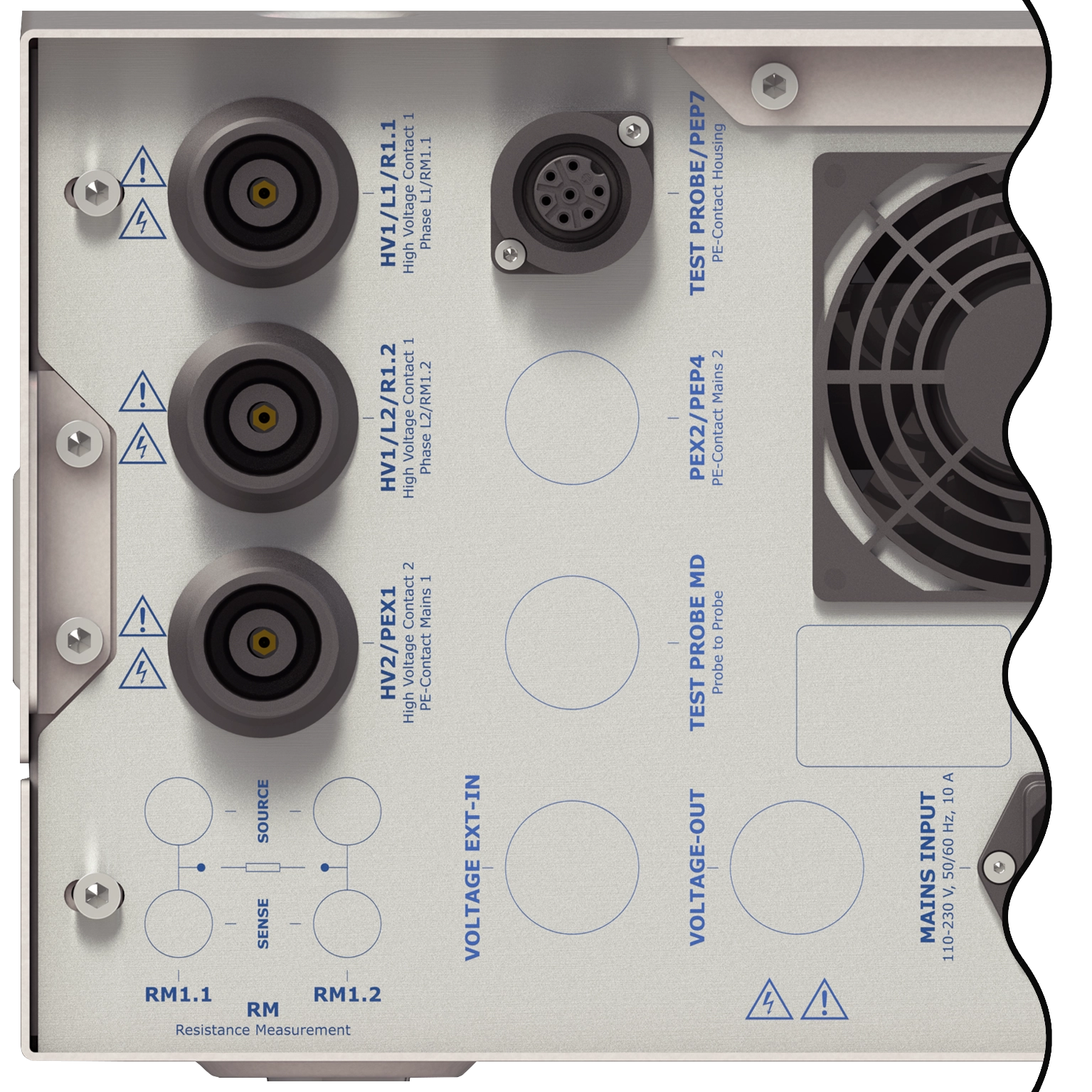
Protective Earth Testing PE-AC/DC 32 A - 500 mOhm
Resistance:
Range:
1 - 500 mΩ
Resolution, digit:
1 mΩ
Measurement uncertainty, accuracy:
1 % of measured value +/- 3 digits
Test Current:
Range:
2.0 - 32.0 A AC/DC (opt. up to 40 A)
Resolution, digit:
0.1 A
Measurement uncertainty, accuracy:
1 % of measured value +/- 3 digits
Wave form:
sinusodial, eletronically generated and regulated
Test Voltage:
Open circuit voltage:
6 - 12 V
Resolution, digit:
10 mV
Measurement uncertainty:
1 % of measured value +/- 3 digits
Resolution, digit:
1 V
Test Time:
Range:
0.5 s - 6 000 s, longer test time optional available
Resolution:
0.1 s
Measurement uncertainty:
+/-10 ms
Start of the test time:
The test time will only be started if the set test voltage is reached
Other:
4-Wire measurement:
Measurement with separated source and sense paths
Minimal test current monitoring:
If the test current drops under a set value the test will abort
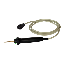
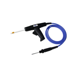
Test probe with start button:
The start button on the test probe can trigger the test (the test current is only supplied when the probe is connected to the DUT)
Test probe with result LED:
The multi-colour-LED on the probe shows the result of the test (red/green)
Leakage Current Test EN 60601 - Medicine
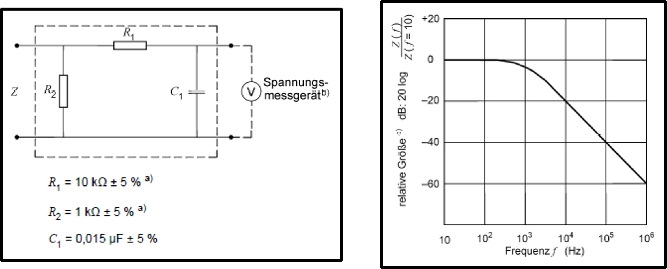
Measurement Circuits and Frequency Respond:
Measurement circuit and frequency response accoring to
DIN EN 60601-1:2013-12, Figure 12
UL 60601-1:2003-04, Figure 15
Low induction components
Impedance ≥ 1 MOhm and capacitance ≤ 150 pF
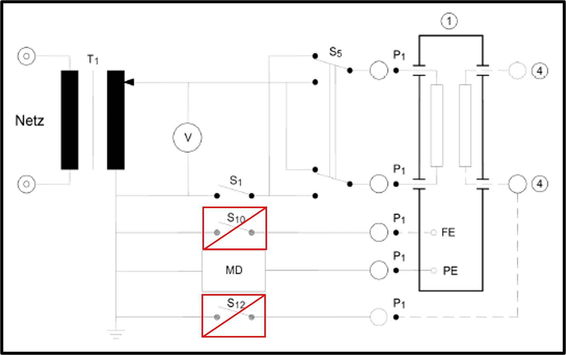
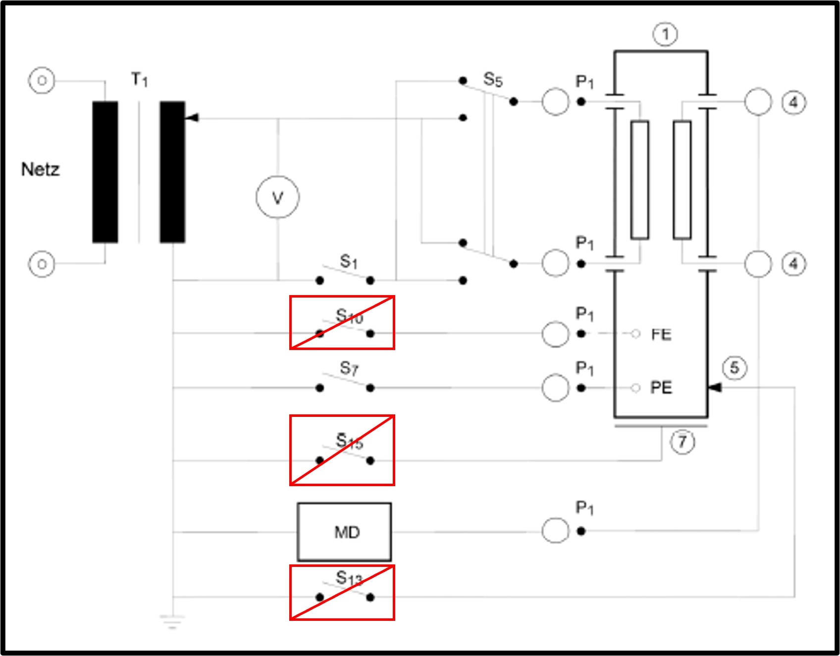
Included Measuring Circuits:
Measuring circuit fur PE LEAKAGE from devices PROTECTION CLASS I with or without application part according to
DIN EN 60601-1:2013-12, Figure 13
UL 60601-1:2013-04, Figure 16
S1: Single-pole switch that simulates the interruption of the outer conductor (first fault / SFC "Single Fault Condition")
S5: Commutator switch for reversing the mains voltage
Without swicth S10 and S12
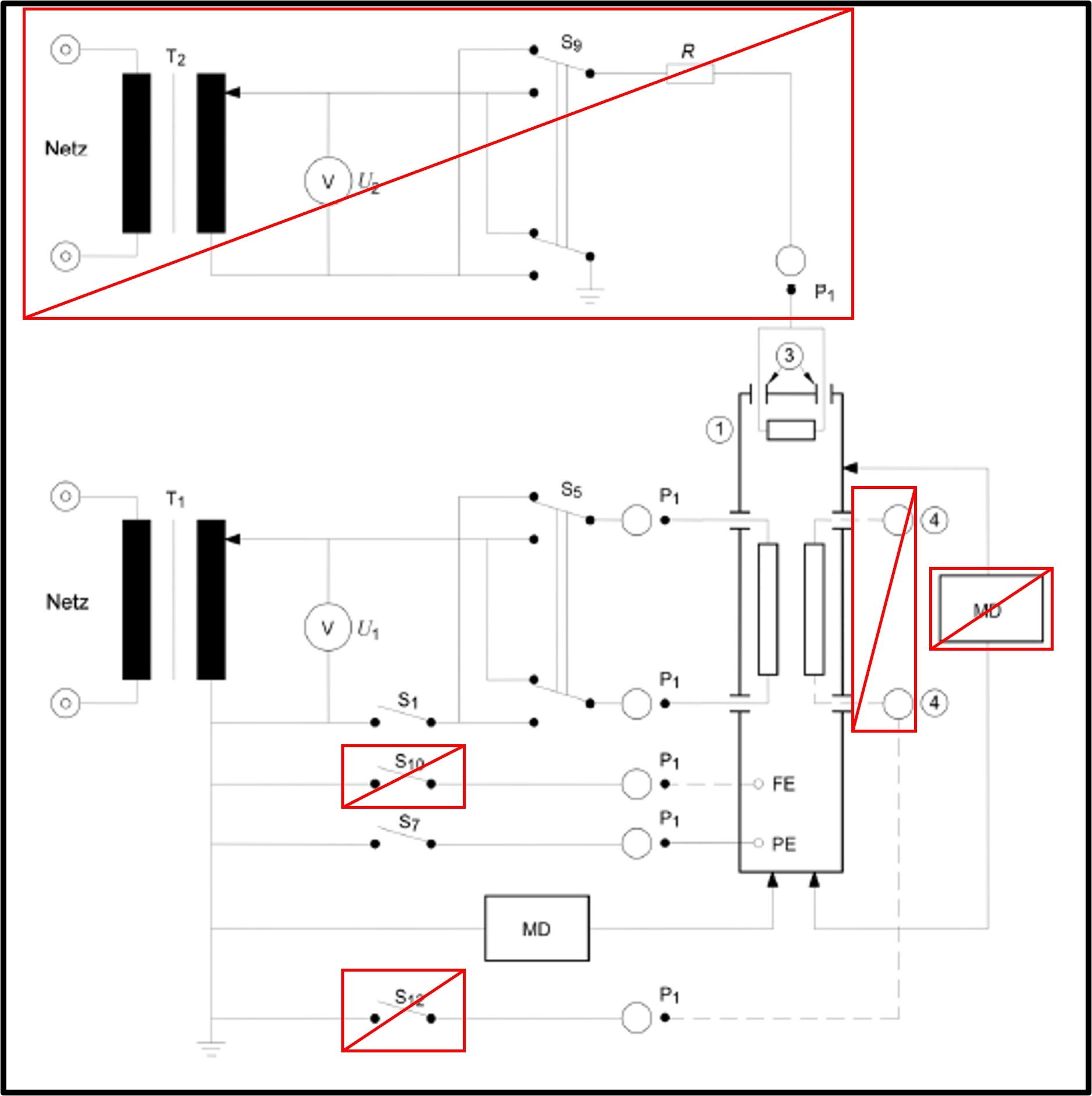
Measuring Circuit for TOUCH CURRENT according to
DIN EN 60601-1:2013-12, Figure 14
UL 60601-1:2013-04, Figure 18
S1: Single-pole switch that simulates the interruption of the outer conductor (first fault / SFC "Single Fault Condition")
S5: Commutator switch for reversing the mains voltage
Without switch S10 and S12
Without connection for:
SIP-SOP "SIGNAL INPUT / SIGNAL OUTPUT"
"PATIENT CONNECTIONS"
"Measuring arrangement housing to housing"
Circuit for PATIENT LEAKAGE CURRENT from the PATIENT CONNECTION to PE according to
DIN EN 60601-1:2013-12, Figure 15
UL 60601-1:2013-04, Figure 20
S1: Single-pole switch that simulates the interruption of the outer conductor (first fault / SFC "Single Fault Condition")
S5: Commutator switch for reversing the mains voltage
Without switch S10, S13 and S15
Without connection for:
"PATIENT CONNECTIONS"
Special Features:
Control:
The included switches and measuring arrangements can be programmed menu-driven in the test plan. In this way, the desired combination of switches and measuring arrangements can be set in each test step. The same functions can also be configured for remote control of the tester via drivers
Dependency:
The AI module BASIC EN 60601-Medicine must be ordered together with the following module:
AI-Module BASIC Voltage Meter 1 MHz (Article: 208849)
AI-Module BASIC EN 60990 - Industry, single phase
Included Measurement Circles:
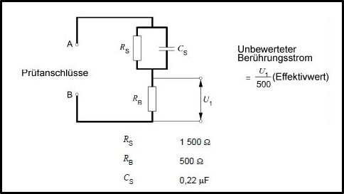
Measuring network for unweighted touch current according to
DIN EN 60990:2015-05, Figure 3
Measuring network for touch current with high frequences causing electrical burn according to
DIN EN 61010-1:2011-07, Figure A.3
DIN EN 61010-31:2008-08, Figure A.3
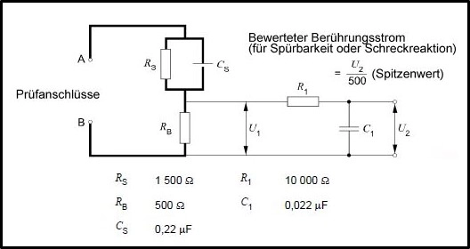
Measuring network for touch current weighted for perception or reaction according to
DIN EN 60990:2015-05, Figure 4
DIN EN 60598-1:2015-10 Figure G.2
DIN EN 60950-1:2014-08, Figure D.1
DIN EN 60745-1:2010-01, Figure 10
DIN EN 60065:2015-11, Figure D.1
DIN EN 61800-5-1:2008-04, sub clause 5.2.3.5
UL 197:2010-03, Figure 46.2
UL 60335-1:2011-10, Figure DVE 1.6.1
Measuring network for alternating current with frequencies up to 1 MHz and direct current according to
DIN EN 61010-1:2011-07, Figure A.1
DIN EN 61010-31:2008-08, Figure A.1
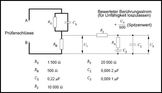
Measuring network for touch current weighted for let-go according to
DIN EN 60990:2015-05, Figure 5
DIN EN 60598-1:2015-10, Figure G.3
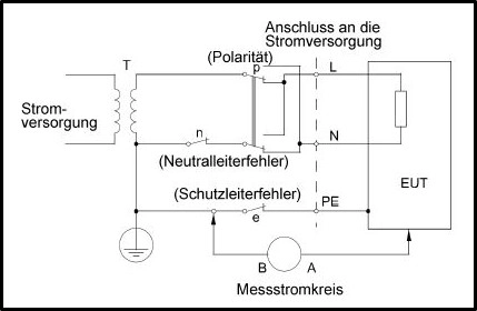
Included Test Conditions:
Test configuration for single-phase equipment on start TN or TT system according to
DIN EN 60990:2015-05, Figure 6
DIN EN 60598-1:2015-10, Figure G.1
Switch n / e: Single-pole switch for interrupting the neutral / PE conductor (first fault / SFC "Single Fault Condition")
Switch p: Switch for reversing the mains voltage
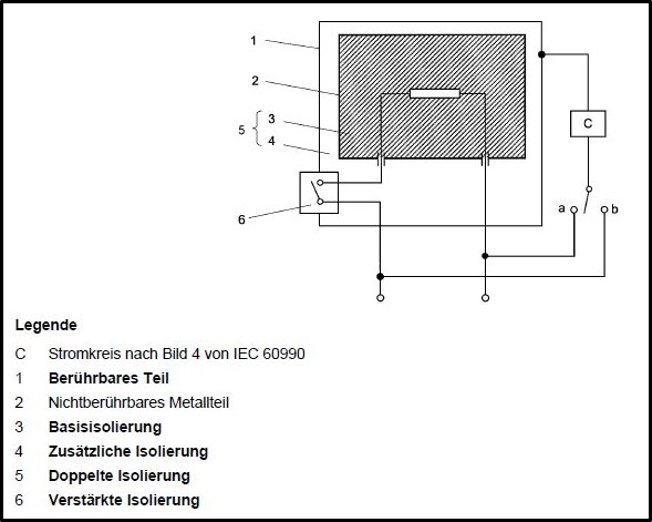
Diagram for leakage current measurement at operating temperature for single-phase connection of devices of protection class II according to
DIN EN 60335-1:2012-10, Figure 1
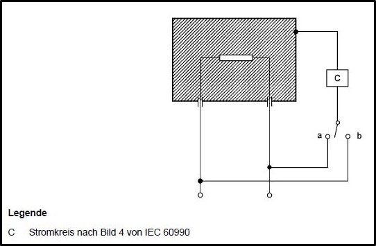
Diagram for leakage current measurement at operating temperature for single-phase connection of devices other than those of protection class II according to
DIN EN 60335-1:2012-10, Figure 2
PE measurement; direct measuring according to
DIN VDE 0701-0702:2008-06, Figure C.3a
DIN VDE 0701-0702:2008-06, Figure C.4b
DIN VDE 0701-0702:2008-06, Figure C.4c
DIN VDE 0701-0702:2008-06, Figure C.4d
Special Features:
Steuerung:
The included switches and measuring arrangements can be programmed menu-driven in the test plan. In this way, the desired combination of switches and measuring arrangements can be set in each test step. The same functions can also be configured for remote control of the tester via drivers
Dependency:
The AI module BASIC EN 60990-Industry must be ordered together with the following module:
AI-Module BASIC Voltage Meter 1 MHz (Article: 208849)
AI-Module BASIC Voltage Meter 1 MHz
Voltage Measurement
Measuring parameter:
RMS (AC+ DC), DC, AC, MIN, MAX
Max. input voltage:
1.5 V - 80 V (peak)
Measurement range 1:
0 mVrms - 400 mVrms
Resolution:
10 mVrms
Measurement range 2:
400 mVrms - 40 Vrms
Resolution:
10 mVrms
Range selection:
automatic
Input resistance:
10 MΩ ± 1 % asymmetric input
Input capacitance:
< 100 pF (including internal wiring)
Method of Measurement
Model:
Voltage drop measurement
AD Converter
16 Bit / 2.5 MSPS Delta Sigma
Calculation
RMS, DC, AC, MIN, MAX values inside the DSP
Scaling
Conversion of measured voltage into current
Current Measurement *
Measurement parameter:
AC, DC, RMS (AC+DC), Peak
Measurement range 1:
1 µA – 400 µA
Resolution:
0.1 µA
Measurement range 2:
0,1 µA – 40 mA
Resolution:
0.01 mA
Base accuracy at 50 Hz:
± 3 % of measured value
Base accuracy at 50 Hz - 100 kHz:
± 3 % of measured value
Base accuracy at 100 kHz - 1 MHz:
± 3 % of measured value **
* Calculated value when the voltage on both ends of a networkis measured at a non inductive resistance of 1 kohm
** Measurements conducted under optimal conditions in a calibration laboratory. The real test environment is of critical importance for high quality measurements, especially at high frquencies (e.g. capacitivecoupling and electromagnetic compatibility)
Test Methods
Test method A:
„DUT connected to mains" (with suitable power supply)
Test method B:
"DUT not operating, L / N have the same potential
Special Features
The AI-Modul BASIC Voltage Meter 1 MHz must be ordered together with one of the following BASIC modules:
AI-Modul BASIC EN 60601-Medicine (Article: 208848), AI-Modul BASIC EN 60990-Industry (Article: 208843)
The AI-Modul BASIC Voltage Meter 1 MHz must be ordered together with one of the following supply modules (FCT-Modules):
Mains voltage supply, External power supply, Regulated internal power supply with variable voltage
GENERAL DEVICE DATA:
Input voltage:
230 V, 50 Hz / 60 Hz
Mains connection:
Schuko plug, IEC connector C14, vertical installation, 10 A, with fuse
Tolerance input voltage:
+/- 10 %
Current consumion:
max. 10 A
Fuse:
10 A, T, 5 x 20 mm, 250 V
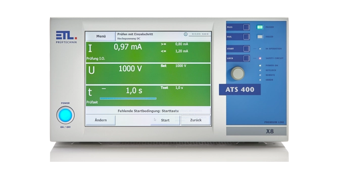
Display:
X2-variant: no display, remote control variant
X4-variant: TFT colour display 5,7“ with touch function
X5-variant: TFT colour display 10,4“ with touch function
X6-variant: no Display, external monitor required
X8-variant: TFT colour display 10,4“ with touch function
Operating system user interface:
X2-variant: remote control only
X4-variant: WIN CE ®
X5-variant: WIN CE ®
X6-variant: WINDOWS ®
X8-variant: WINDOWS ®
Storage of test plans and results:
X2-variant: storage through higher-level control
X4-variant: locally on SD card, optionally USB or LAN
X5-variant: Optionally locally on SD-CARD, USB or LAN
X6-variant: Optionally locally on SD-CARD, USB or LAN
X8-variant: Optionally locally on SD-CARD, USB or LAN
Setting of the test parameters:
Manually in the individual test menu or via test plan (DataView user interface) or fully automatically via interface (ASCII, DLL, .NET)
Error signaling:
acoustically, visually and via interface
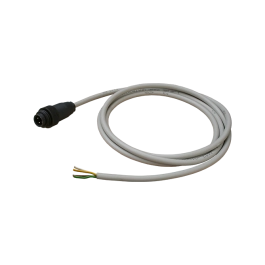
Standard equipment on delivery:
instruction manual, mains cable, safety circuit plug
Calibration:
factory calibration including calibration certificate
DAkkS calibration optional available
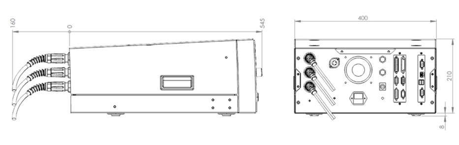
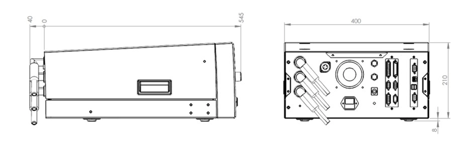
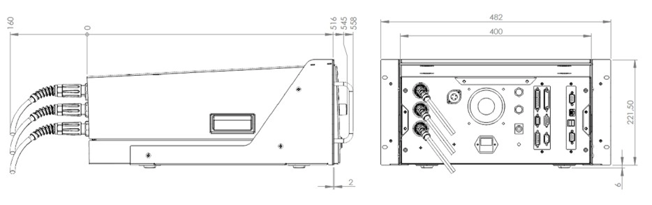
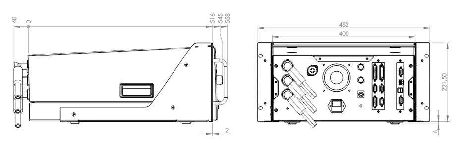
Casing:
Metal case, RAL 7035
Weight:
depending on the modules installed, from 25 to 35 kg
Environmental conditions:
Casing:
IP20
Humidity:
max. 80 %, not condensating
Permitted temperature range:
+ 5 up to + 40 °C
Max. altitude above sea level:
2 000 m
Cooling:
active cooling
Electric safety and standards:
EN 61010-1:
Safety requirements for electrical quipment for measurement, control, and laboratory use
EN 61326-1:
Electrical equipment for measurement, control, and laboratory use - EMC requirements
EN 61000-3-3 / EN 61000-3-2:
Electromagnetic compatibility (EMC)
EN 50191:
Erection and operation of electrical test equipment
EN 60598-1:
Luminaires / Part 1: General requirements and tests
Pollution degree:
2
Protection class:
1
Advanced device setup:
User administration:
individually configurable
Signal configurator:
individual configuration of digital result outputs
Data manager for test plans and results:
individual setting of storage options, storage location, naming of the result file, and automated creation of result directories
Buzzer options:
individual configurations of acoustic signals
Basic settings of the test system:
language selection, device name, interfaces configuration
Start of the user interface:
individual setting of thedesired start menu (e.g. start directly in the test plan selection menu via barcode)
Selection of test programme:
manually via selection window, process-safe via barcode or keyboard, via digital interface orby reading out a transfer file
Manager for dummy testing:
Dummy test is automatically requested according to configuration (e.g. at programme start, at userchange, via digital interface, after a certain number of test objects, at a certain time or after a time interval
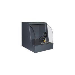
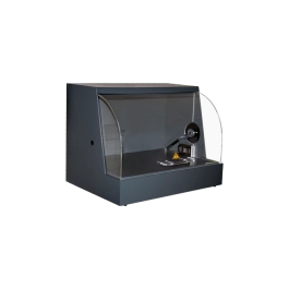
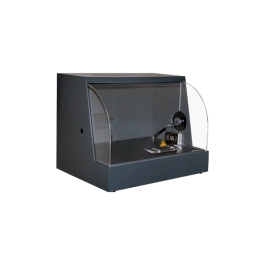
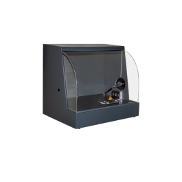
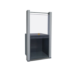
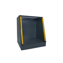
Locking options for safety testing cages:
individual setting of the locking options (during the test, on good, on bad, ...)
Start Options for Testing:
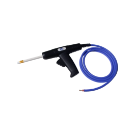
Start and stop signal through test pistol *:
Special automated start in 4-wire technology. The start of the test (switiching on the test voltage) only takes place when both test pistols are safely contacted (depending on the test types)
Start via safety circuit:
The test is started by locking the safety circuit
Start button on the devic:
The test is started by pressing the button on the front of the device
Start via contact monitoring *:
start only when contact is made ( source and sense connected) and there is no cable break - permanent monitoring
Start via serial nterface:
Start via higher-level control (PLC or PC)
Start via digital interface:
start via digital IO such as PLC, footswitch, push button, etc. ...
Start options:
individual setting of start modes
(*) patented:
The ETL contact monitoring is a patented procedure:
German patents: 100 11 466.0 and 100 11 345.1
European patents: 01 105 568.8 and 01 105 567.0
Interfaces:
ETL Interface / Digital IO:
Start, stop, result GOOD, result ERROR, and test running, etc. (all digital outputs are designed with wear-free semi conductor components)
RS232 / LAN PC Interface *:
Remote control interface for customer´s own applications or for data management package ETL DataView
CAN Interface:
to expand the test system for supplementary features and further external expansion stages
LAN Interface *:
for connection to the customer´s own network, e.g. for storing test results, depending on the operating variant
USB Interface *:
for connection of further storage edia as well as keyboard and mouse, depending on operating variant
VGA connection *:
for connection of an external screen, only X6- and X8-variant
* The installed interfaces depend on the operating variant, see illustration "Operating Variants"
Connections - Safety Components:
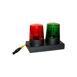
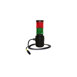
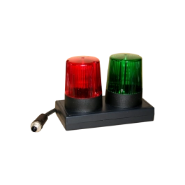
Signal lamps:
Connection of a signal lamp combination (green / red) according to EN 50191
Safety circuit:
With appropriate wiring, 3 different standard-compliant safety circuits can be implemented by the customer:
- Testing with test pistols
- Testing with safety testing cages / two-hand control
- Testing in an automation solution / production line
USER Interface / Digital IO, optional:
digital interface for freely programmable inputs and outputs (all digital outputs are designed with wear-free semi conductor components)
Analogue IO, optional:
4 analogue inputs for recording analogue signals (0 - 10 V DC)
2 analogue outputs (D/A), e.g. for result monitoring
Frequency IO, optional:
4 frequency inputs for detecting speeds and their direction of rotation